Anycubic Kobra Max Heating Element Debug
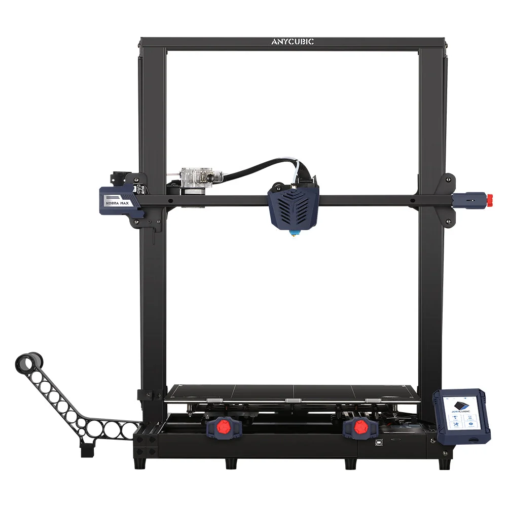
This write-up documents a live debug of an Anycubic Kobra Max that refuses to heat the bed. The machine throws Hotbed heater abnormal, please check it and wiring, then stops. The work so far maps the power path, identifies the hotbed adapter board, and shows that the power MOSFET can still switch when driven manually — which points the fault toward the control / enable path rather than a dead heater pad.
Printer
| Field | Value |
|---|---|
| Model | Anycubic Kobra Max |
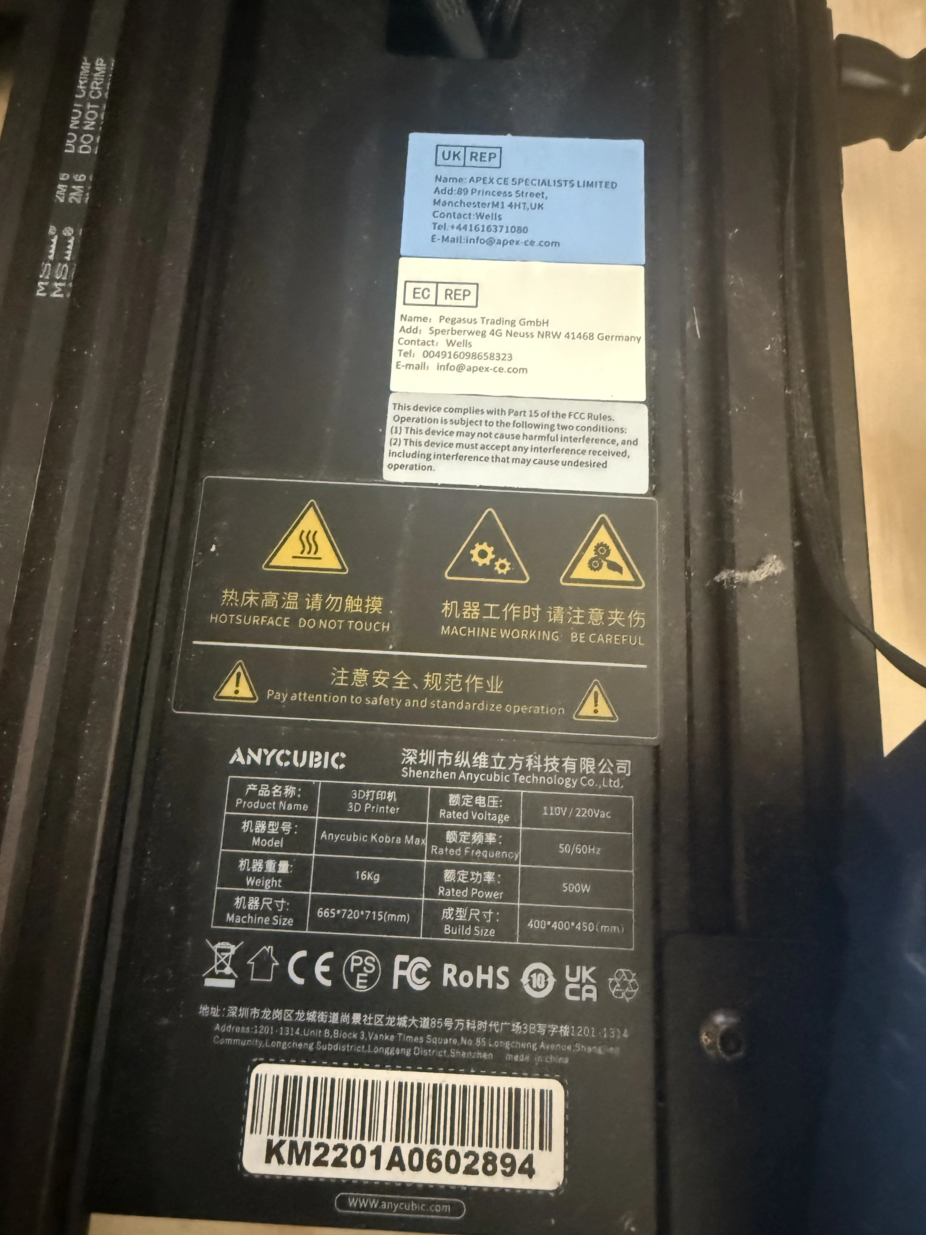
| Serial | KM2201A0602894 |
| Build volume | 400 × 400 × 450 mm |
| Machine size | 665 × 720 × 715 mm |
| Power | 500 W, 110 / 220 V AC |
| Maker | Shenzhen Anycubic Technology Co., Ltd. |
Symptom
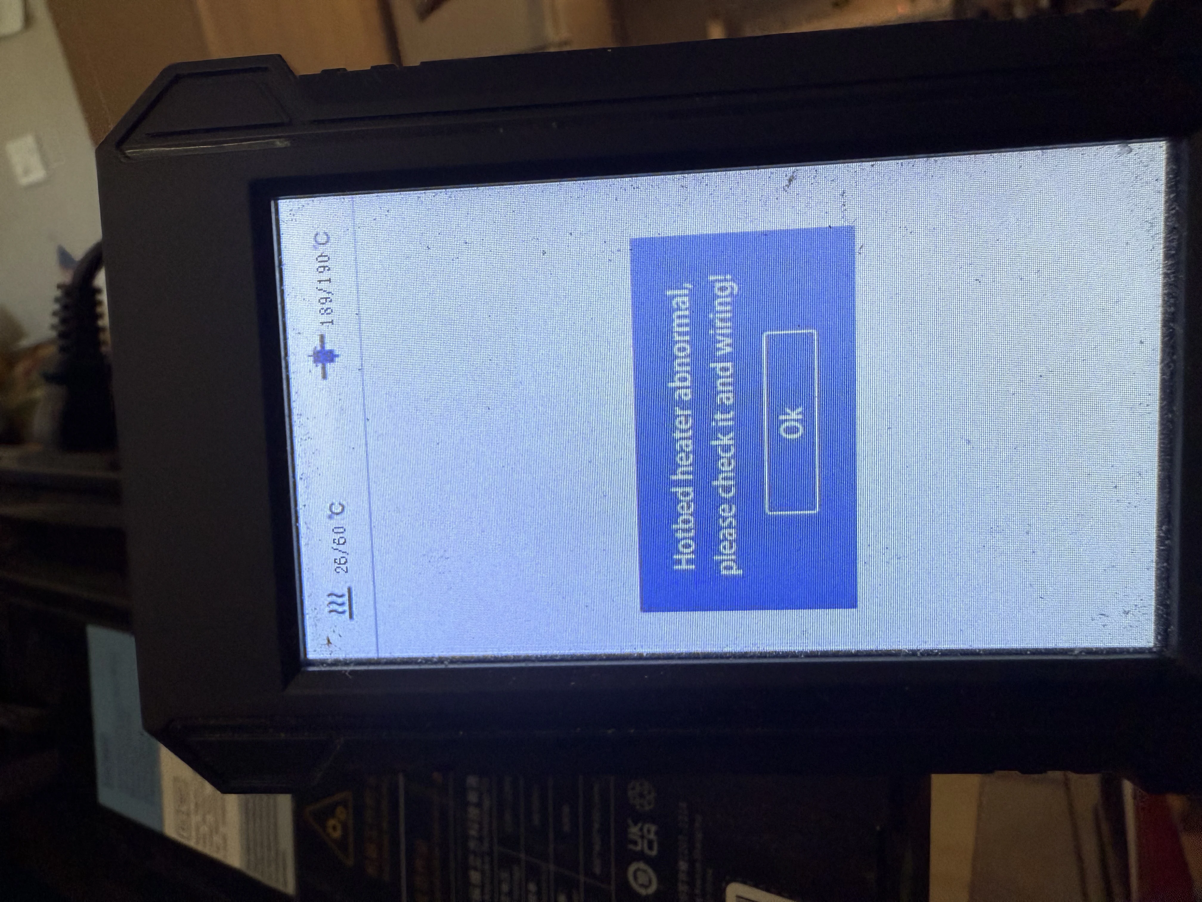
With a bed target set (for example 60 °C for PLA), the display stays near ambient and the printer raises the fault dialog. Nozzle control can still look normal while the bed path fails.
How the bed is supposed to work
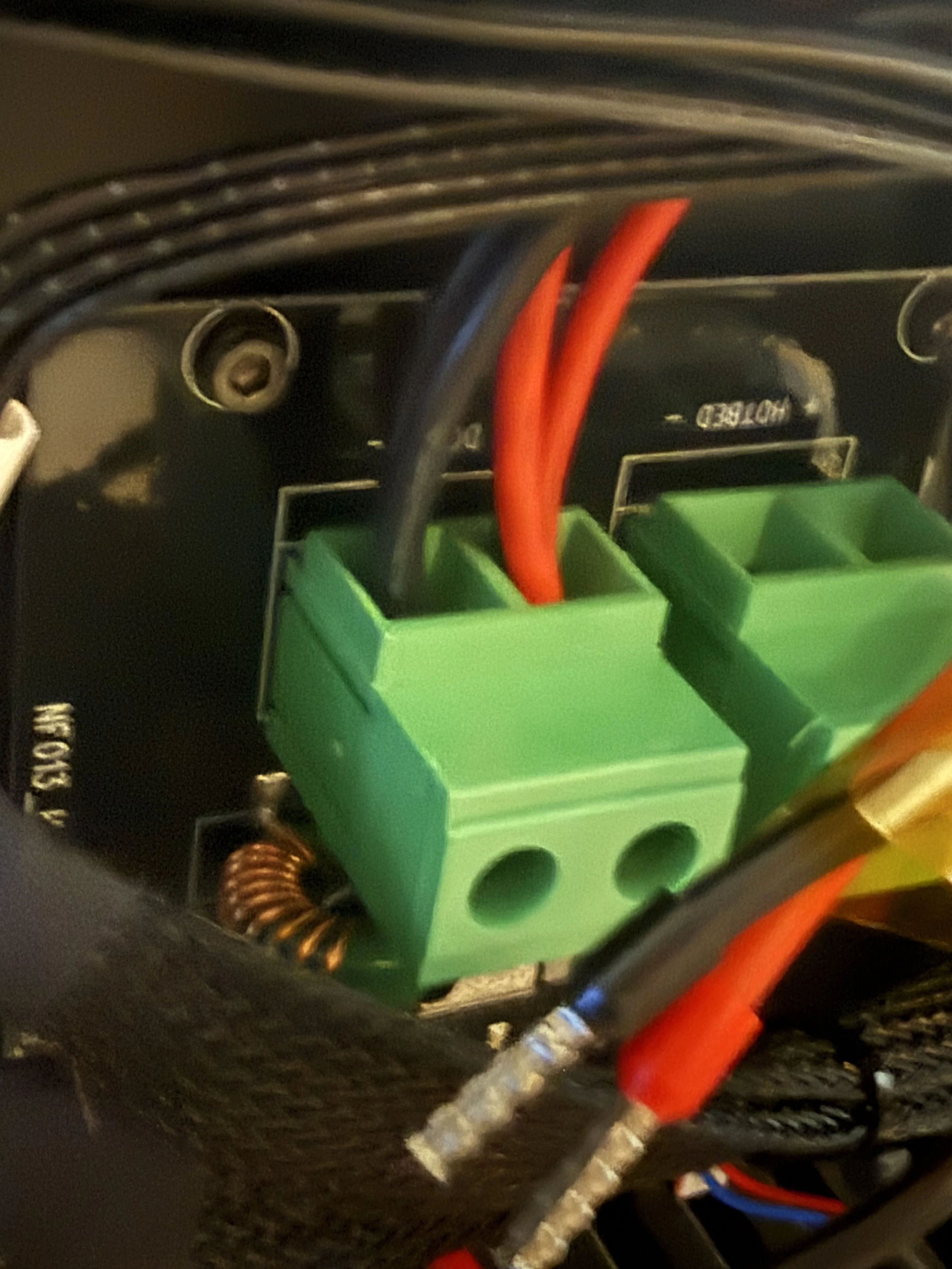
The heated bed is not driven directly by the mainboard high-current rails. Thick wires carry heater power; thin wires are the NTC thermistor (temperature sensor). On this machine, a separate hotbed adapter board sits between the PSU and the heater pad. The mainboard only provides a low-current CONTROL enable. The board MOSFET switches ~24 V on and off (PWM hold) — 24 V is not “25 °C.”
- Thick wires — heater pad power path
- Thin wires — NTC thermistor (resistance falls as temperature rises; ~100 kΩ at ~25 °C)
- CONTROL plug (red / blue) — enable from mainboard into the adapter board
- MOSFET — low-side (or similar) switch that actually connects the pad
Bed power voltage guide
| State | Across bed + / − |
|---|---|
| Not heating | ~0 V |
| Heating hard | ~24 V |
| Holding temperature | May pulse / lower average (PWM) |
On low-side switch designs one wire can still read ~24 V to ground when idle. The useful reading is the difference across the two thick heater wires. Black is not always chassis 0 V.
Quick fault pattern table
| Pattern | Likely cause |
|---|---|
| 0 V across bed while commanded to heat | MOSFET / adapter board / enable path |
| Voltage OK, pad never warms | Heater pad open or wrong pins |
| Voltage dies mid-heat | Board overheat, protection, bad crimp |
| Nonsense temperature on screen | NTC / thin sensor wiring |
Board identification
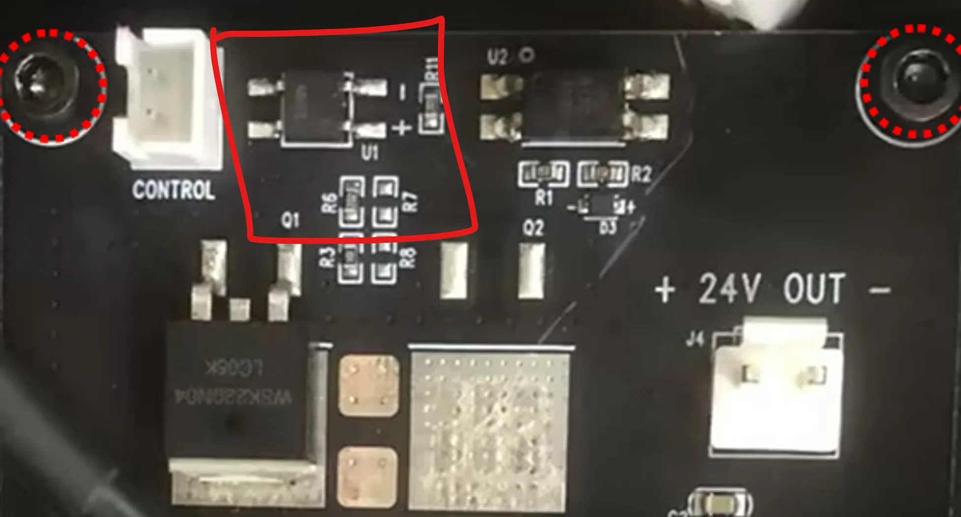
Photos of the electronics bay show two distinct boards: the large Anycubic mainboard and a smaller
adapter labeled NF013_Heating-Platform (silkscreen also shows version marks such as
V0.0.2 / related revisions). That smaller board is the bed power switch, not the mainboard.
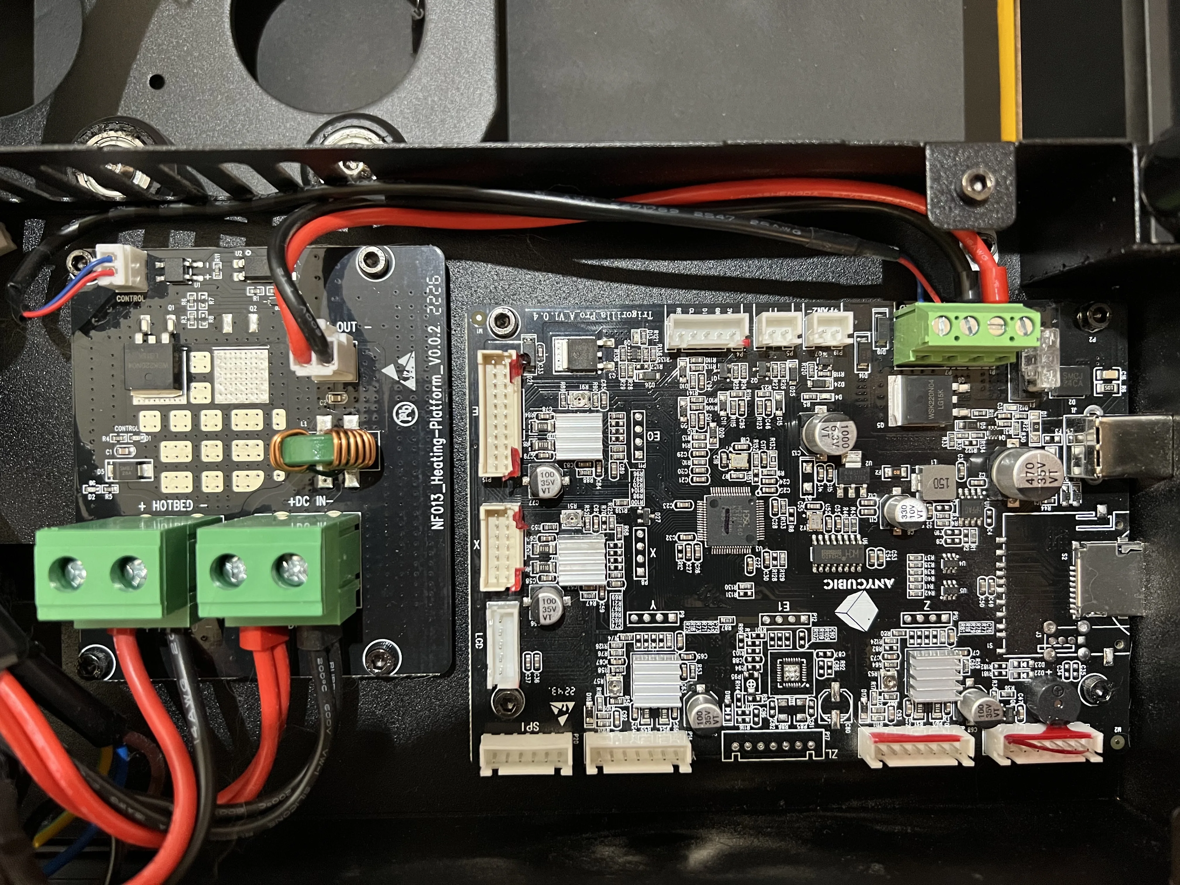
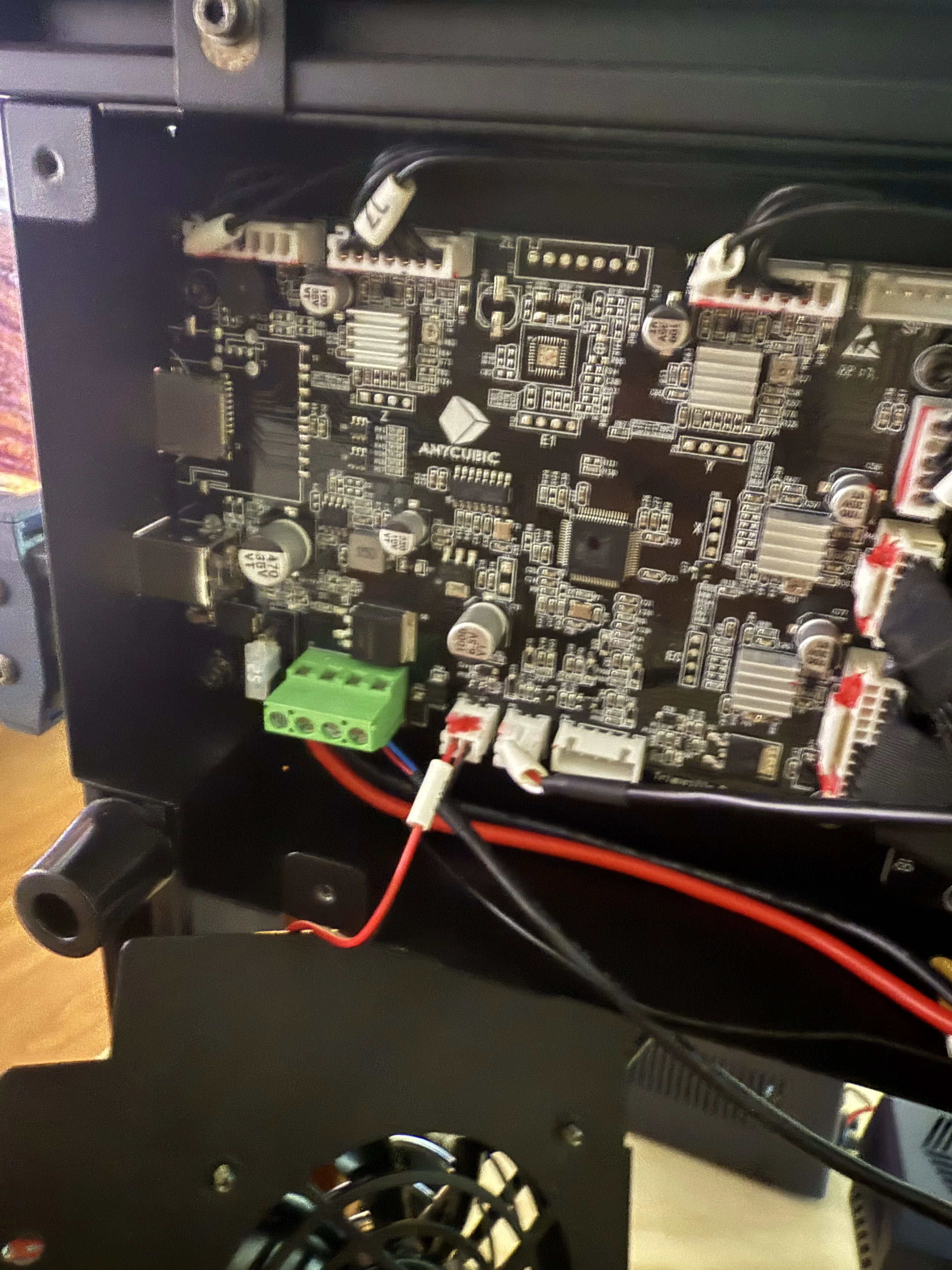
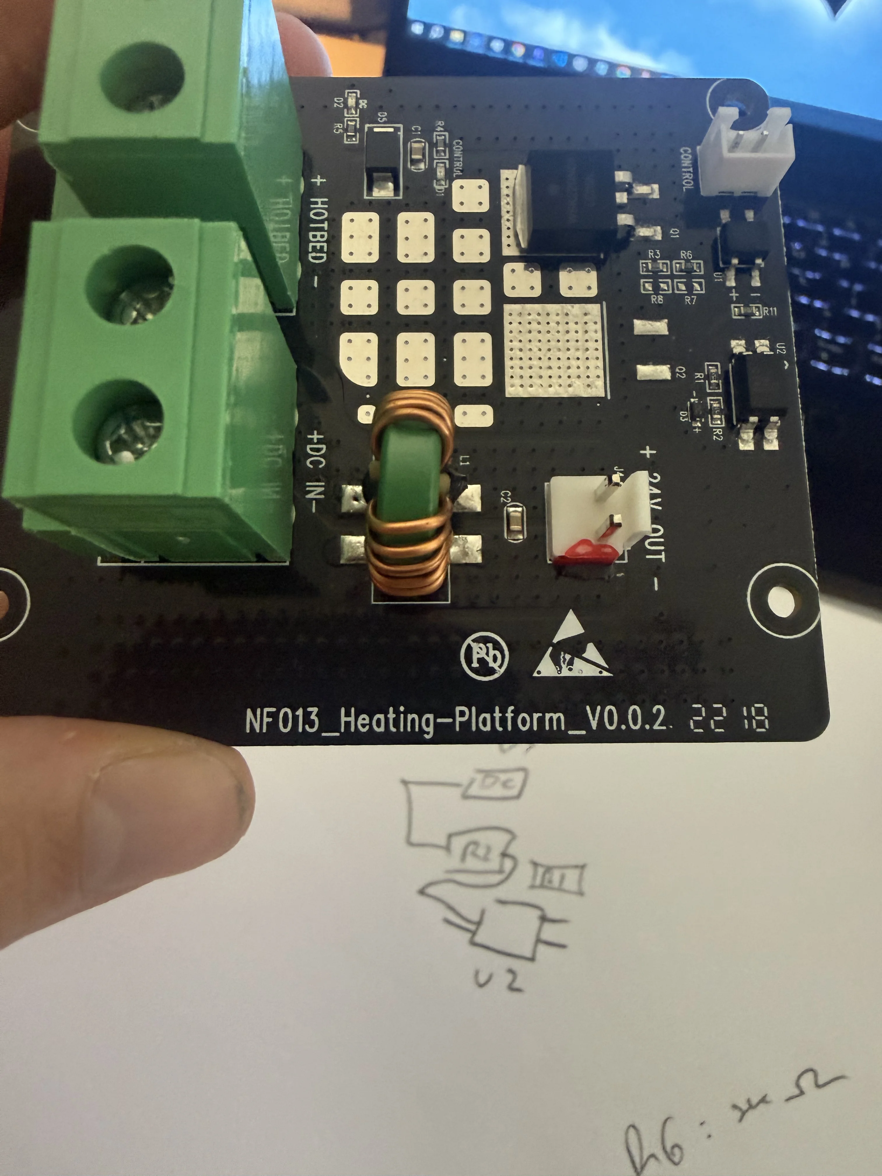
NF013_Heating-Platform_V0.0.2.
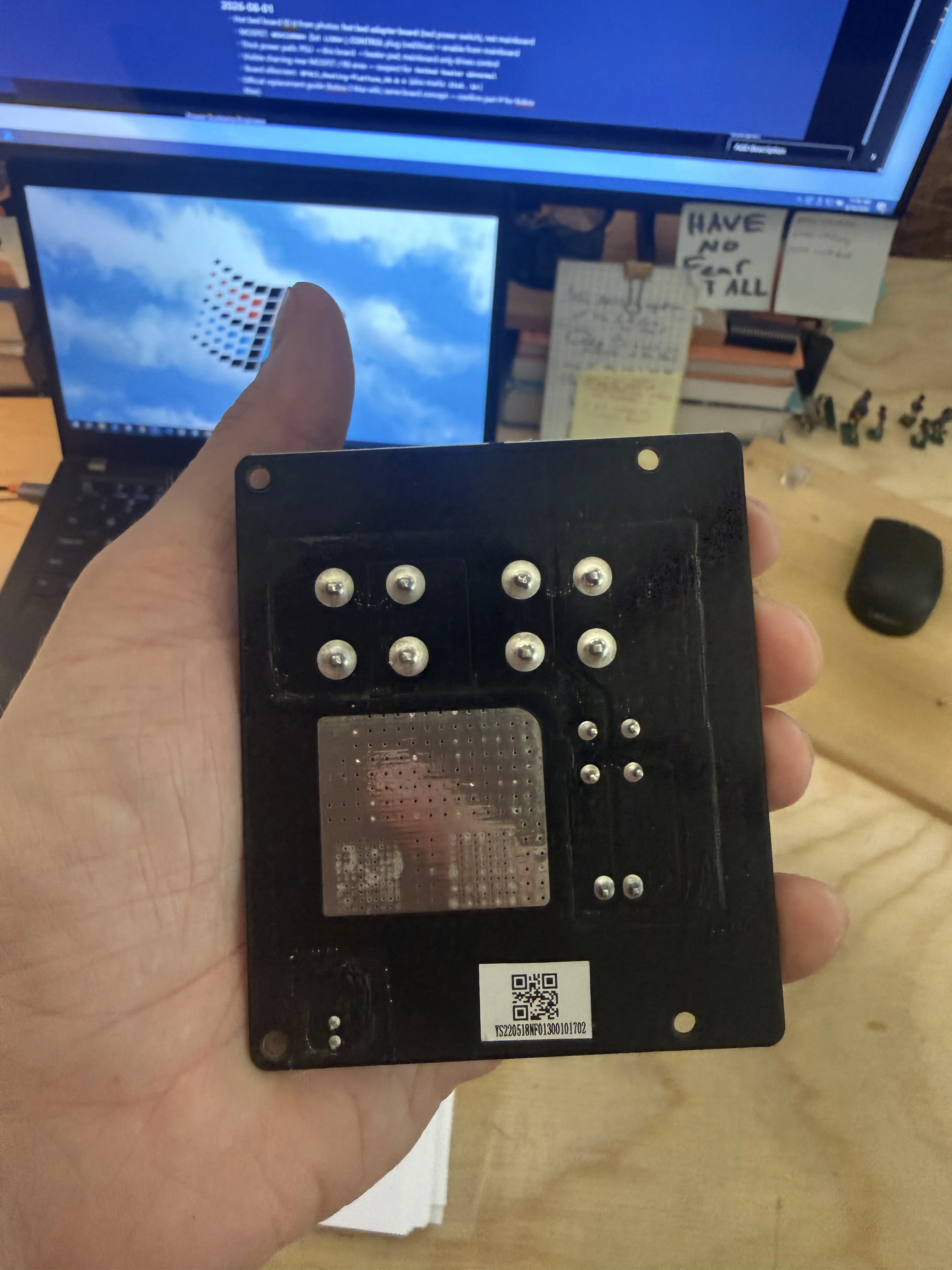
YS220518NF01300101702). No dense SMD field on this face.
Anycubic publishes a hotbed adapter replacement guide for the related Kobra 2 Max family (same board concept — confirm part number before ordering for the original Kobra Max):
Key components
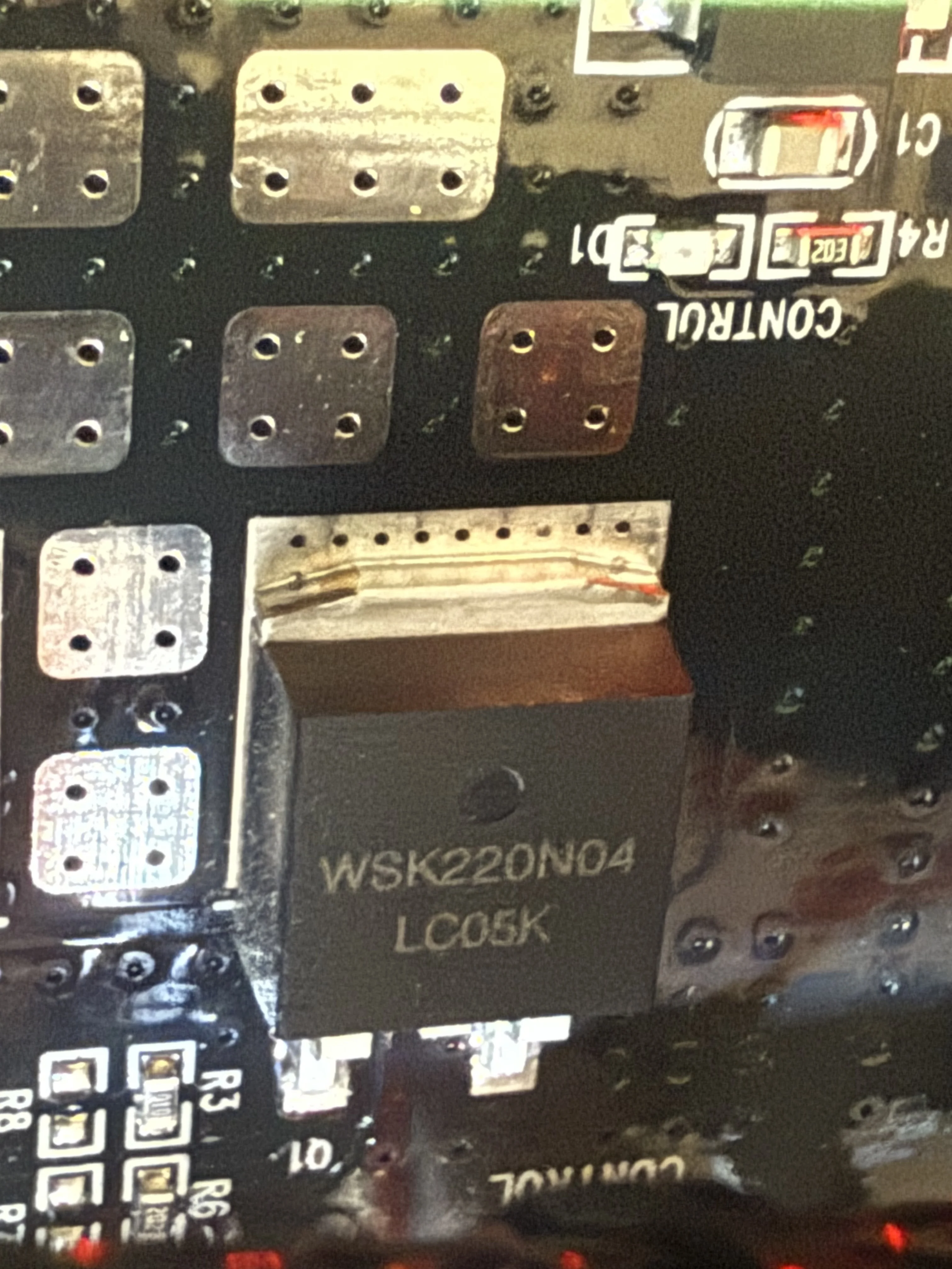
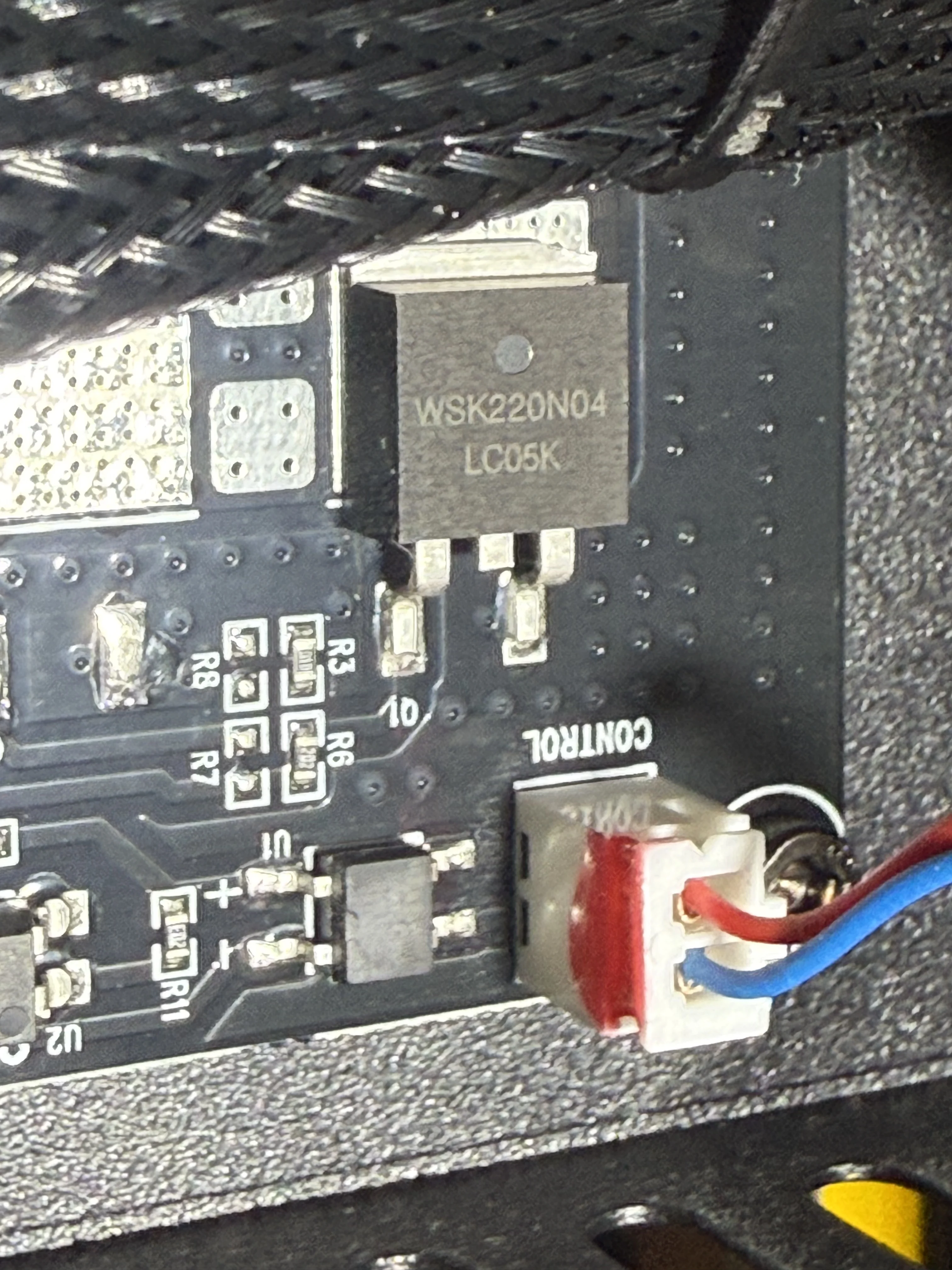
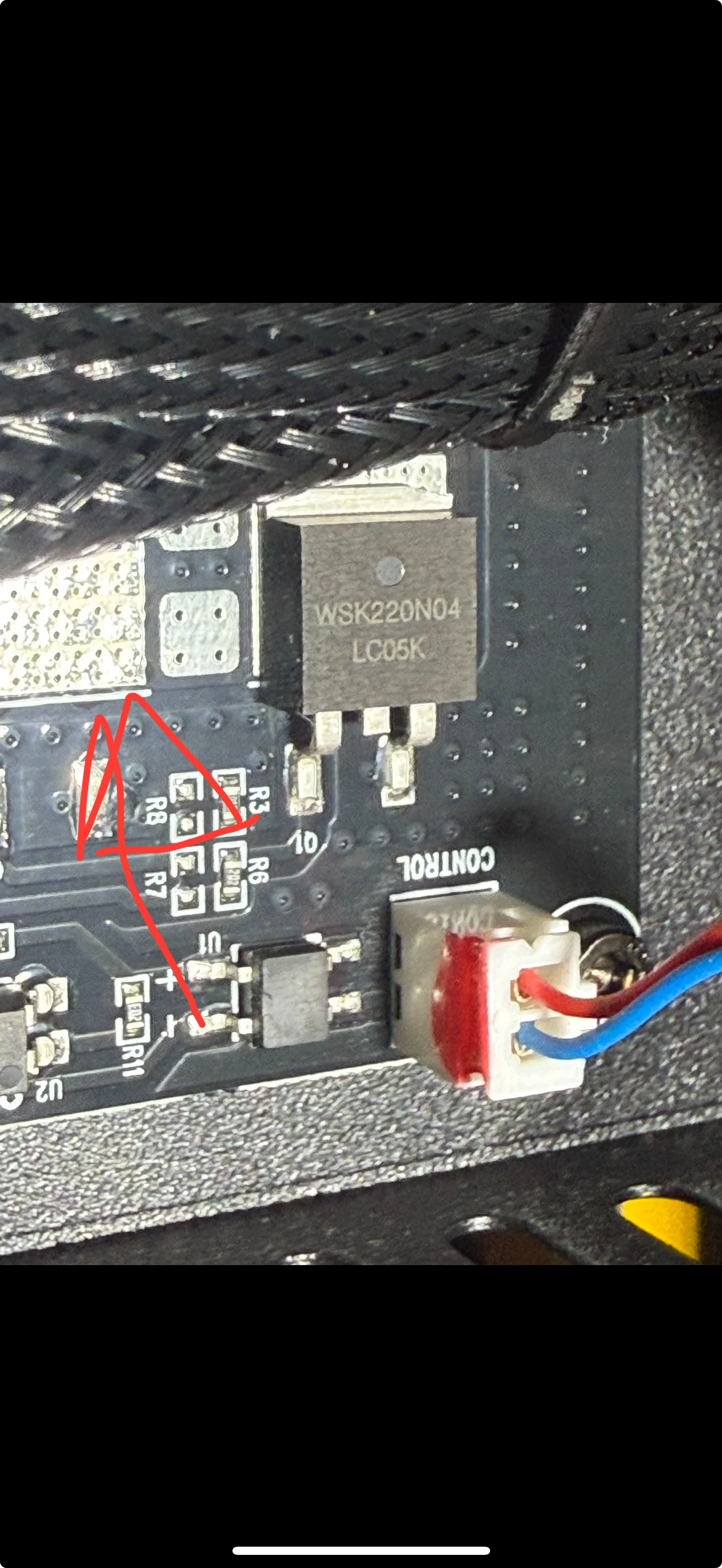
WSK220N04 power MOSFET
The large package on the adapter is marked WSK220N04 / lot LC05K. This is the
high-current switch that connects bed power when the gate is driven hard enough.
EL817 optocoupler (U1)
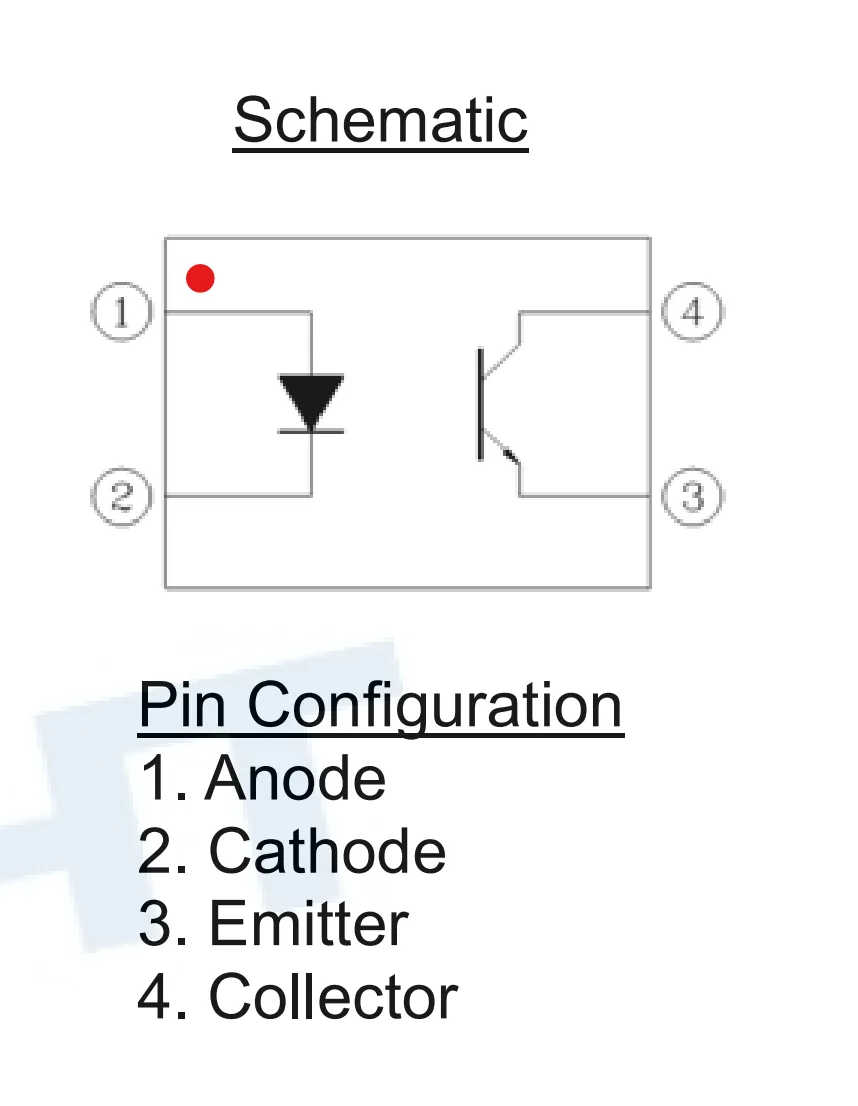
U1 is the isolated CONTROL front-end: an EL817-class optocoupler. The mainboard drives the LED side; the phototransistor side (collector on pin 4) participates in turning the MOSFET on. Light carries the binary on/off decision across isolation.
Debug log
2026-07-26 — setup and first pass
- Identified printer from label: Kobra Max, serial KM2201A0602894.
- Logged the hotbed heater abnormal fault and walked heater pad / NTC / MOSFET possibilities.
- Installed UltiMaker Cura 5.13.0 with the Anycubic Kobra Max profile for later test prints (PLA first).
- Bed voltage guide written: idle ~0 V across +/−; heat ~24 V.
2026-08-01 — board ID and FET forced ON
Confirmed the small board is the hotbed adapter (bed power switch), not the mainboard. Thick power path: PSU → adapter → heater pad; mainboard only drives CONTROL.
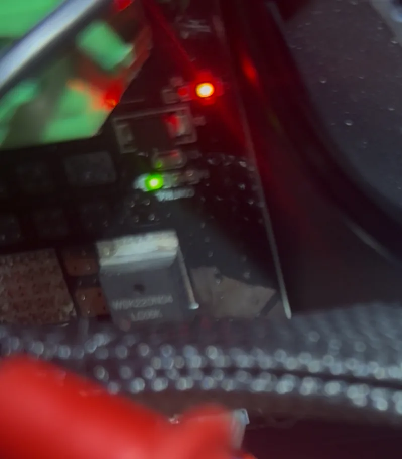
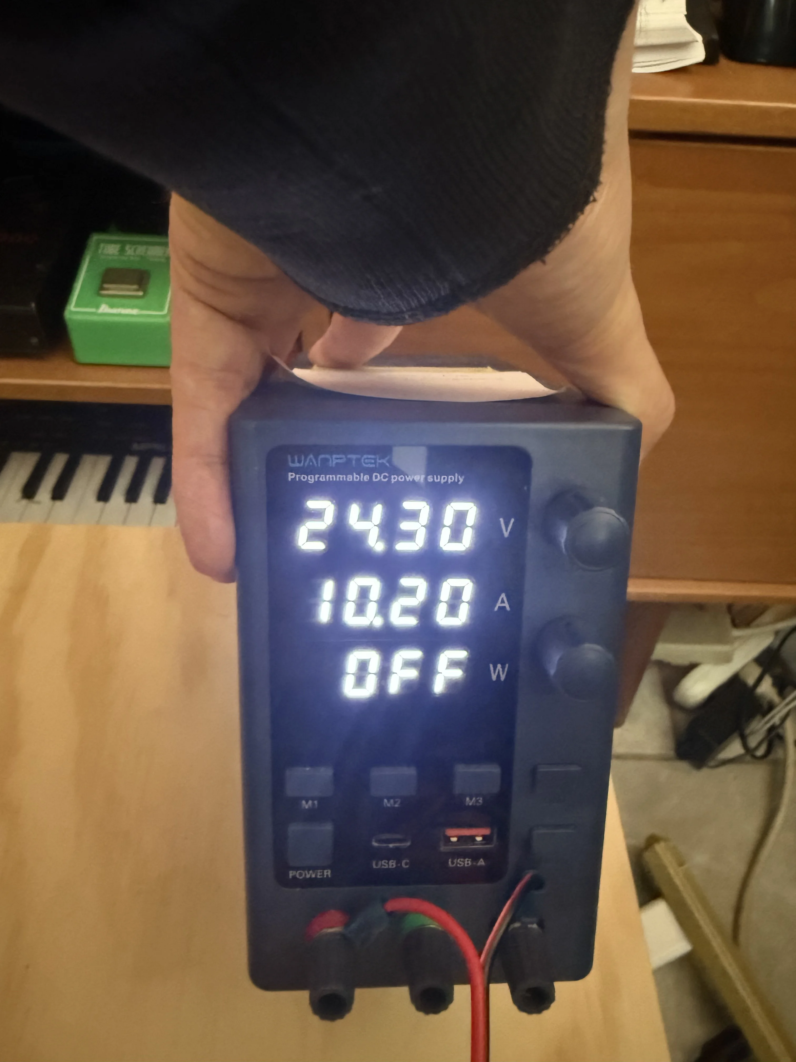
Field measurements with the unit on, probing the heater negative terminal relative to ground, showed about 22.4 V present — supply side alive. Manually applying ~10 V on the FET gate (VGS well above a few volts) turned the channel on: the green indicator lit, drain-to-source conducted, and the pad began to take current from the negative 24 V path. Drain node dropped toward roughly 4.3 V under that drive (stronger VGS would likely pull it lower).
VGS field check (gate to source / GND)
| Measured gate (to source / GND) | Expect |
|---|---|
| ~0 V | Bed OFF — no pass |
| ~2–6 V while “heating” | Drive problem / partial ON — danger zone |
| ~8–12 V while heating | Good ON — pass |
Takeaway: the FET itself can switch. The open question is where the normal ~10 V-class gate drive is generated (or lost) on the CONTROL / U1 path under mainboard command.
2026-08-10 — board removal
Board pulled to inspect the backside and continue hunting the gate-drive origin. Still open: exact generation path of the ~10 V that successfully forced the FET on during the August 1 test.
Datasheets
- WSK220N04 MOSFET datasheet (PDF)
- EL817C optocoupler datasheet (PDF)
- MB8S bridge rectifier datasheet (PDF)
Next steps
- Trace CONTROL from the mainboard through U1 to the MOSFET gate under a commanded heat cycle.
- Measure VGS while the UI requests 60 °C — compare against the forced-on values.
- Check for open resistors, burnt pads, or failed optocoupler around the R8 / U1 / CONTROL island.
- If the control chain is dead, replace the hotbed PCBA; if the pad is open, swap the heater element.
- After repair: PLA benchy calibration print (Cura Kobra Max profile already installed).
Photo gallery
Select an image to view it full size.